Introduction and Goals
In the final ENGS 26 project, our goal was to use skills learned in the class to balance an inverted pendulum that is inherently unstable when perturbed from equilibrium. This was accomplished through math modeling the dynamics of the car and pendulum, testing the transient behavior of the car parts (motor, sensor, etc), and doing root-locus analysis to make our system stable. After two hard-working weeks, my teammate and I were able to make a working car that balances our pendulum.
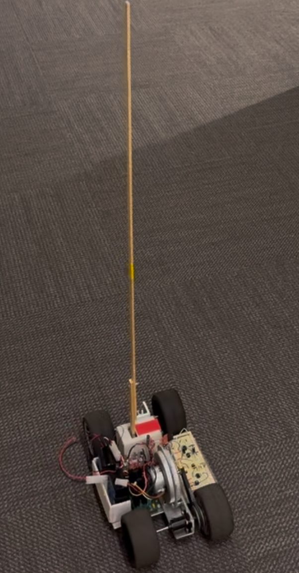
Math Modeling and Approach
To begin the math-modeling process, my partner and I made several assumptions to make the modeling manageable. The most important and significant assumption we made was that the pendulum arm must be in the linear range. This system can quickly become super nonlinear super quickly, but we decided to work with very small-angle perturbations to approximate sine(x) to x. This assumption and physical setup allowed the model to be significantly simpler. Another important assumption was that the pendulum arm’s mass can be approximated to be in the center of mass since the mass of the stick was significantly less than the chassis. Lastly, we assumed that the car’s movement will be applied as a torque directly on the pendulum arm without any significant losses.
We tried to get the differential equations in two methods. The Euler-Lagrange equations and torque balance. To me, torque balance makes a bit more sense since we build the equations up with the intuitive equations of Newton. With this, we were able to make the block diagram that eventually led us to success. Many of the transfer functions for the blocks were found in the lab, which won’t be discussed in detail here. Theta/Tau represents the differential equation found by torque balancing.

Root-Locus and Compensator Design
To make our system respond quickly while removing steady-state error to 0, we chose to use a PID controller. These specifications were desired considering that the pendulum is starting at an unstable solution. This means that a steady-state error of 0 is necessary for the pendulum to stop moving. The derivative part of the controller was also crucial. It was implemented to improve the transient performance, which essentially allows for anticipation of the pendulum arm and reduce overshoot and settling time.

Results
Credit: Rana Moeez Hassan for being a great help on the circuitry and being an amazing lab partner, Dr. Laura Ray for instructing the course and answering all of our questions, and Bob Barry for fixing any lab issues and for being patient with us.